|


click here to download file

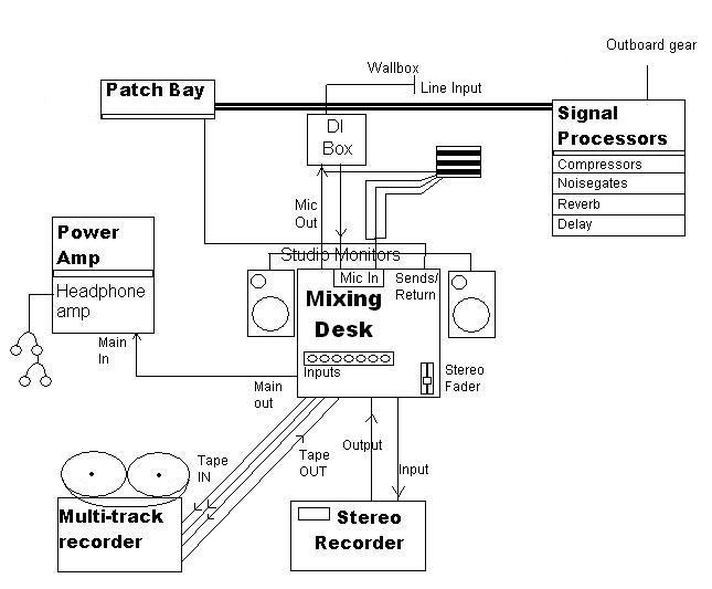
A Typical Studio Layout
Mixing Desk
The desk has two main sections: Inputs and Outputs. Although most sound desks look terrifying initially, they can be mentally
broken down into simple sections. Once you understand the basic concepts, you'll see that all mixing desks are very similar.
Inputs are where the sound signals come into the desk, and outputs are obviously where the sound leaves the desk.
Any input signal (in the case above, there are 8 possible inputs) can be routed to any of the four outputs.
Input channels:
Gain controls the sensitivity of the channel to the incoming sound. A low level microphone signal will require a high
gain level. A higher input (from a CD player, for example) will need little or no gain.
Equalisation (EQ) controls are used to adjust the tonal quality of the sound. Most mixing desks have two or three EQ
controls for high, middle and low frequency sounds.
Auxiliaries can be used for additional routing of sound to external devices.
Routing switches control which of the outputs the sound is sent to.
Pan control positions the sound in the stereo "image" of the output.
Fader is used to control the volume of sound sent to the output. Most faders are calibrated in decibels, so that with
the fader at the bottom, it's at infinity (i.e. no sound gets through). The optimum position for the fader is around 70% of
the way up. This is normally marked 0db, and means the desk electronics are neither amplifying or attenuating (reducing) the
signal - it's at it's optimum.
Output channels:
The inputs sent to each output are mixed together, and once the output channel is raised, the signal is sent to the output
connector.
Multi-track recorder
The machine that actually records musicians' performances during a session. The multi-track recorder is kept in the control
room and operated by the engineer(s). Often, the process of recording onto a multi-track recorder is called tracking or laying
tracks.
Each track can be used to record a different instrument or vocal performance. Because the tracks are synchronised, performances
that have already been recorded may be played back and listened to while additional performances are recorded.
Consequently, a "perfect" recording can be achieved without requiring all participating musicians to perform perfectly
together. If one musician makes a mistake, he can listen to the recording of the others while re-performing his own part.
The most common multi-track recording method is using the computer program 'ProTools' through a Macintosh computer.
Stereo Recorder
This machine is similar to the multi-track recorder except instead of many mono tracks, its just one big 2 channel track;
Left and right. Not used very often on its own, but in studio stereo channels are activated with microphones such as overheads;
two overhead speakers go into the same stereo channel.
Signal Processors
The devices collectively known as signal processors were originally added to the recording studio to allow compensation
for frequency response or dynamic range problems in the equipment. When carefully used, they can add to the fidelity of the
sound, and occasionally improve on reality. If improperly used, they can seriously degrade the sound or even produce laughable
results. It is possible to use signal processors to manipulate sounds, so naturally they are popular with composers of electronic
music.
EQUALIZATION (E.Q.)
An equalizer is a device that can alter the spectral content of a signal. This can be done with any circuit that has an
adjustable frequency response, the most familiar being the tone controls on a home stereo set. These tone controls typically
affect the amplitude in two frequency regions, the treble and bass. This is sufficient for the minor changes the end user
may wish to make in the program, but the recording engineer needs more flexibility and coverage of the entire audio spectrum.
The complete studio will have complex e.q. systems that might include 30 or more regions of control. Many of these machines
have sliders to adjust the amplitude of each band, and those sliders are laid out in such a way that their positions visually
indicate the frequency response. This feature gives rise to the name GRAPHIC EQUALIZER.
A 30 band equalizer is going to be an expensive device, simply because of the sheer duplication of circuitry. Much of this
circuitry is wasted most of the time because typical use only involves adjustment to two or three bands while the others are
left alone. An equalizer with bands of adjustable frequency is a more economical approach to the problem, because only three
to five circuits are necessary. Such an equalizer is called a PARAMETRIC EQUALIZER. Parametric equalizers typically have three
controls for each band, allowing adjustment of frequency, amplitude, and width of the band.
COMPRESSION
It is also possible for the soft spots of a program to become too low in amplitude, especially in a noisy medium like AM
radio. A program with a wide dynamic range may have to have that dynamic range reduced in order to fit a particular audio
system. (Surprisingly, the current switch to digital audio is making this problem more common as stations try to fit the wide
range of compact discs through the restricted dynamic window of FM transmitters.) A device which reduces the overall dynamic
range of a signal is called a COMPRESSOR.
A compressor works by measuring the average amplitude of the input signal and using the information from that measurement
to control the gain of an amplifier. If the measurement comes out above an adjustable threshold, the gain is reduced, if the
measured input amplitude is below the threshold, the gain is increased. The amount of effect is usually adjustable and is
expressed as a ratio of input dynamic range to output dynamic range, such as 2 to 1 or 3 to 1.
The release time is adjustable just as with the limiter, but the adjustment is much more critical, because the compressor
is constantly changing gain whereas the limiter only cuts in occasionally. It is impossible to find a release time that is
perfect for all situations. A very short release time will cause the circuit to attempt to trace the waveform of low frequency
components of the signal, resulting in inter-modulation distortion of high frequency components; whereas a long release time
will leave the amplifier in the wrong mode if the signal changes quickly. That second error results in brief bursts of expansion,
a very disconcerting effect. (Sounds like heavy breathing.)
NOISE GATING
Sometimes a program is encountered which has proper dynamic range but which has objectionable background noise. Very little
can be done to reduce the noise without affecting the signal, but the spaces where there is no signal can often be cleaned
up with a NOISE GATE. This circuit is an expander that only works on the low amplitude parts of the signal. Any section that
is below the threshold will be attenuated rather drastically, so the space becomes nice and quiet. You can hear this device
in action on old movies on TV. Release time adjustment is very critical in this application also, because if the circuit is
too slow, the turning down of the noise will be painfully obvious, but if the circuit works too fast, the reverb at the ends
of the sounds will be lost.
REVERB
Reverberation is the result of the many reflections of a sound that occur in a room. From any sound source, say a speaker
of your stereo, there is a direct path that the sounds covers to reach our ears. But that's not the only way the sound can
reach us. Sound waves can also take a slightly longer path by reflecting off a wall or the ceiling, before arriving at your
ears. A reflected sound wave like this will arrive a little later than the direct sound, since it travels a longer distance,
and is generally a little weaker, as the walls and other surfaces in the room will absorb some of the sound energy. Of course,
these reflected waves can again bounce off another wall before arriving at your ears, and so on. This series of delayed and
attenuated sound waves is what we call reverb, and this is what creates the 'spaciousness' of a room.
DELAY
The delay is one of the simplest effects out there, but it is very valuable when used properly. A little delay can bring
life to dull mixes, widen your instrument's sound, and even allow you to solo over yourself. The delay is the also a building
block for a number of other effects, such as reverb, chorus, and flanging.
Simply put, a delay takes an audio signal, and plays it back after the delay time. The delay time can range from several
milliseconds to several seconds. Figure 1 presents the basic delay in a flow-graph form. This only produces a single copy
of the input, and thus is often referred to as an echo device.
Patch Bays
Patch bays can be viewed as the nerve centre of any studio. They are used
to route signals between pieces of equipment in cases where a variety of routings may be required. Signals which will always
be routed in a particular way need not go via a patch bay and can be ‘hard-wired’. Standard ¼" jack patch bay
PCBs allow signals usually routed in a particular way to be ‘normalised’, for example the MIX OUT will usually
be connected to the input of your stereo recorder. Strictly this is half normalising. Half normalising allows the source,
to be paralleled, or split, to feed two inputs if a jack plug is inserted into the output socket, but breaks the link if a
plug is inserted into the destination socket. Full normalising would be broken if a jack plug was inserted into either the
normalised source or destination.
Studio Monitors
Speakers used in the control room of a recording
studio. Generally of two types: Main Monitors for overall sound, and Reference Monitors used to check sound quality through
less capable speakers, such as might be found in domestic environments.
Power Amplifiers
An amplifier used
to drive significant power levels. An audio amplifier that drives a loudspeaker and the final stage of a transmitter are common
examples.
DI boxes
DI box stands for Direct Injection. The electric guitar produces
an electrical signal, so it can be plugged right into the mixing console - no microphone is needed. Because the mix and guitar
amp are bypassed, the sound is clean and clear, it lacks distortion and colouration or the amp.
You need a DI box because
there is a frequent requirement to interface equipment that has basically non standard unbalanced outputs with the standard
balanced inputs of mixers, either at line level or microphone level. An electric guitar, for example, has an unbalanced output
of fairly high impedance - around 10 kilo ohms or so. The standard output socket is the 'mono' quarter-inch jack, and output
voltage levels of around a volt or so (with the guitar's volume controls set to maximum) can be expected.
Plugging the guitar directly into the mic or line level input of a mixer is unsatisfactory for several reasons:
the input impedance of the mixer will be too low for the guitar, which likes to drive impedances of 500 kilo ohms or more;
the guitar output is unbalanced so the interference-rejecting properties of the mixer's balanced input will be lost;
the high output impedance of the guitar renders it incapable of driving long studio tie-lines;
and the guitarist will frequently wish to plug the instrument into an amplifier as well as the mixer, and simply using
the same guitar output to feed both via a splitter lead electrically connects the amplifier to the studio equipment which
causes severe interference and low-frequency hum problems.
Similar problems are encountered with other instruments such as synthesisers, electric pianos, and pickup systems for acoustic
instruments.
To connect such an instrument with the mixer, a special interfacing unit known as a DI box (DI=direct injection) is therefore
employed. This unit will convert the instrument's output to a low-impedance balanced signal, and also reduce its output level
to the milli-volt range suitable for feeding a microphone input. In addition to the input jack socket, it will also have an
output jack socket so that the instrument's unprocessed signal can be passed to an amplifier as well. The low-impedance balanced
output appears on a standard three-pin XLR panel-mounted plug which can now be looked upon as the output of a microphone.
An earth-lift switch is also provided which isolates the earth of the input and output jack sockets from the XLR output,
to trap earth loop problems.
The simplest DI boxes contain just a transformer, and are termed 'passive' because they
require no power supply. The transformer in this case has a 20:1 step-down ratio, converting the fairly high output of the
instrument to a lower output suitable for feeding microphone lines. Impedance is converted according to the square of the
turns ratio (400:1), so a typical guitar output impedance of 15 kilo ohms will be stepped down to about 40 ohms which is comfortably
low enough to drive long microphone lines. But the guitar itself likes to look into a high impedance.
The active DI box replaces the transformer with an electronic circuit which presents a constant very high impedance to
the instrument and provides a constant low- impedance output. The box is powered either by internal batteries, or preferably
by the phantom power on the microphone line.
Headphone amplifiers
A headphone amp is an alternative to a standard home hi-fi
amplifier for those that use headphones a lot, the main advantage of a headphone amp is that since the power requirements
of a headphone are quite small the designer can usually spend quite a bit more on the amplification components than they can
when designing a normal amplifier, meaning that for little money, you can get a sound quality that really approaches high
end ideals. Equally, a well designed headphone amplifier should also drive headphones that cheaper amps and systems have problems
with and have a reasonable damping factor which is often more important for headphones, resulting in a vastly improved sound.
And please note that a headphone amplifier is not to be called a Head Amplifier.
A headphone distribution amp however is intended to drive a number of headphones, usually in a some sort of a professional
situation such as a recording studio or a language lab etc., the emphasis in the design of a distribution amp is usually more
on cost per channel that on sound quality although there are some excellent quality distribution amps out there designed for
use in recording studios
no
|